SPIRIT LIFT
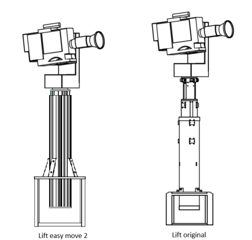
In this documentation we will detail the setting up of a Spirit LIFT column with a Spirit HEAD head.
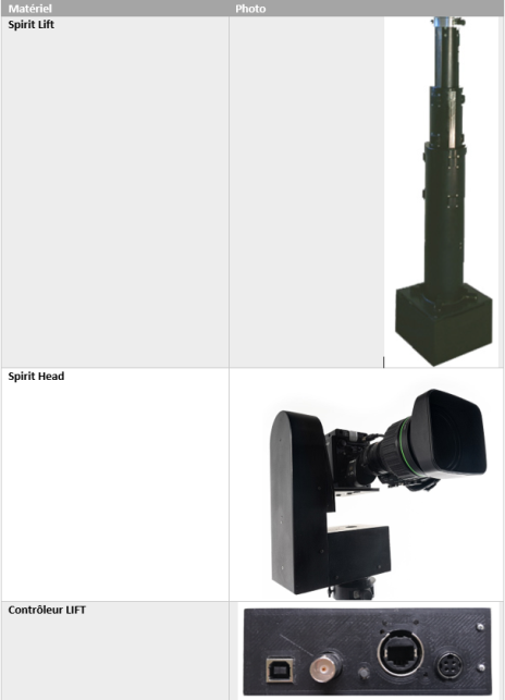
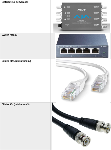
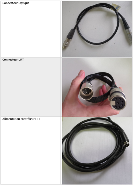
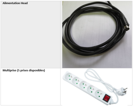
Necessary material
Here is a pictorial list of the necessary equipment
Facility
Setting up Head
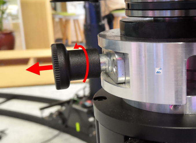
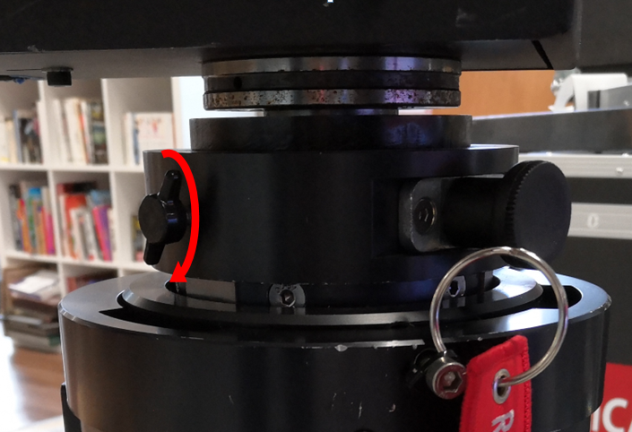
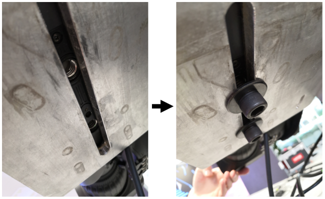
To set up the Spirit Head on the lift, lock the 2 pins in the open position by pulling them and turning them 90°
Then place the head on the lift, making sure to align the holes as in the photo below
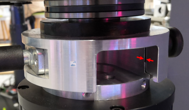
Replace the pins by turning them the other way. If the Head is correctly placed, the pins sink into the lift and hold it in position. Finish by tightening the small screw located between the 2 pins (see photo below)
Setting up the camera
Place the camera with its Optics on the Head so as to center its weight on the platform. (The equilibrium position is as horizontal as possible). This step is important to limit the effort on the tilt motor. Attention however, Depending on the geometry of the optics, the travel around the tilt can be reduced. It is then necessary to limit via the web interface the stroke to avoid damaging the optics.
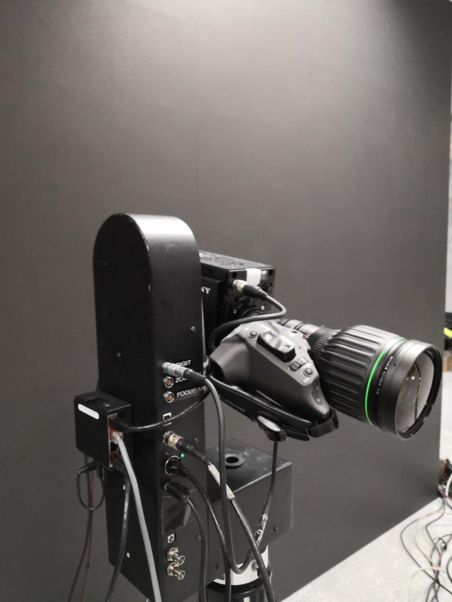
Once the camera is correctly positioned, tighten the screws under the camera to secure it to the Head as in the photos below.
Connections
Installation diagram
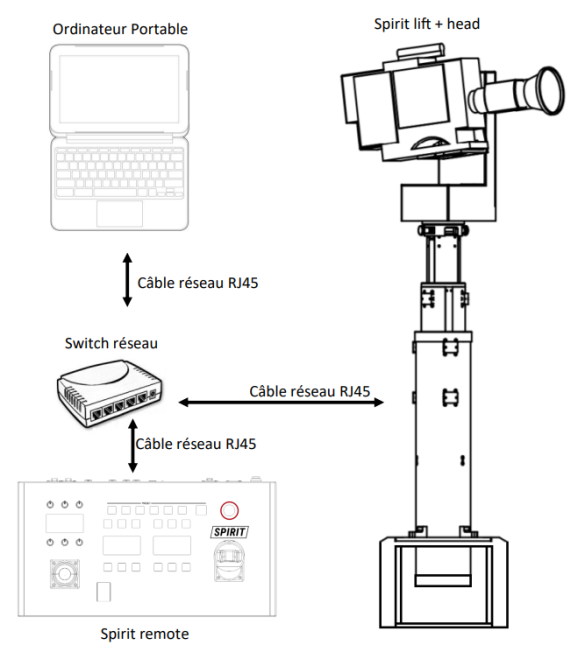
The connections to be made are summarized in the following diagram (the connections at the camera level depend on the configuration. Here we place ourselves in the case requiring the most cables, that is to say with an IP camera):
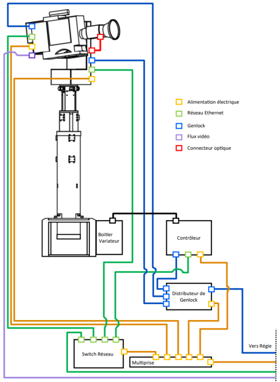
In the configuration on the previous page, a Genlock distributor and a network switch are used. However, all these elements can be positioned in the control room if you have long enough cables.
Connection at head level
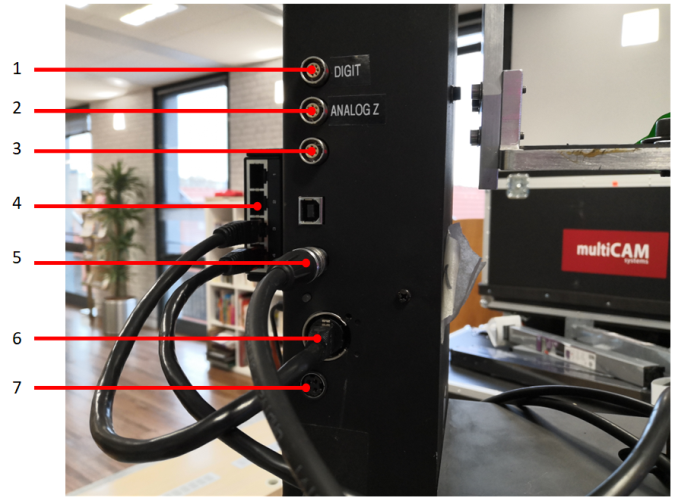
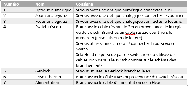
The photo and table below summarize the connections to be made at the Spirit Head
Camera and optical connections
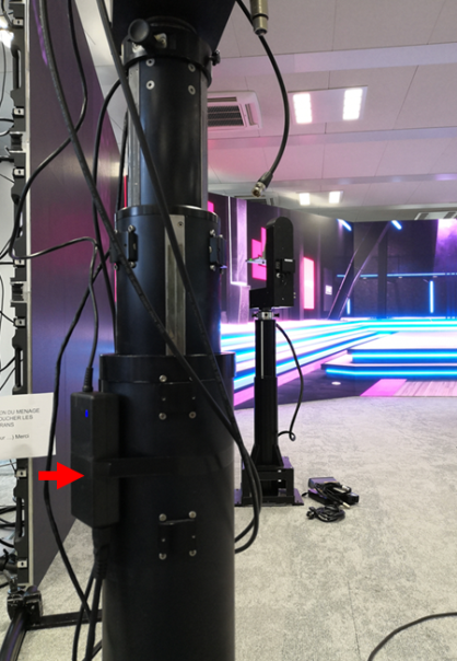
The connections are specific to the camera used. It is possible that the camera power cable is too short when the lift column is at its maximum amplitude. In this case, the power supply must be placed as close as possible to the camera by taping it to the column, for example:
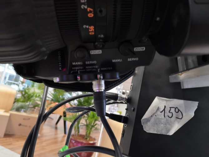
If you have digital optics, the photo below details where the digital optics cable from the Head connects:
Column level connections
Genlock
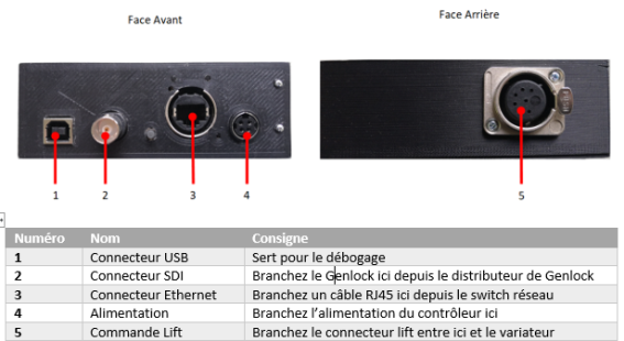
If you use the Genlock, you need 2 boxes: 1 "generator" box which will generate the signal and 1 "amp distribution" box which will allow you to repeat and distribute the signal. They look like this:
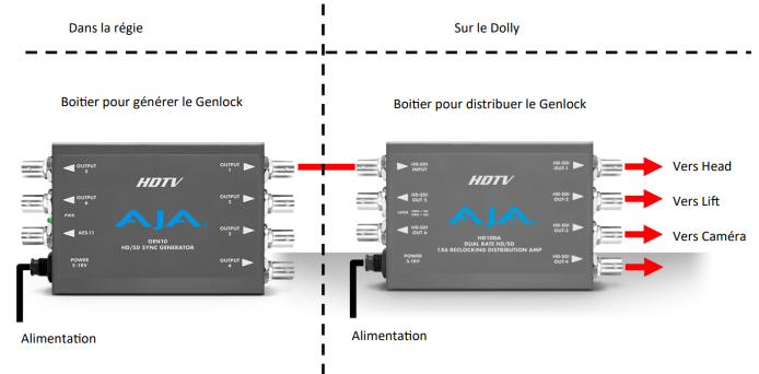
The diagram above shows a possible wiring of Genlock. The first box that generates the signal is located in the control room so that it can be used on other devices. It is connected by an SDI cable to the second box which allows the Genlock to be redistributed on the Head, the Lift and the camera.
Network Setup
There are multiple possible configurations to control the lift. We will detail here how to access the web interfaces of the lift and the Head.
Setting up the network
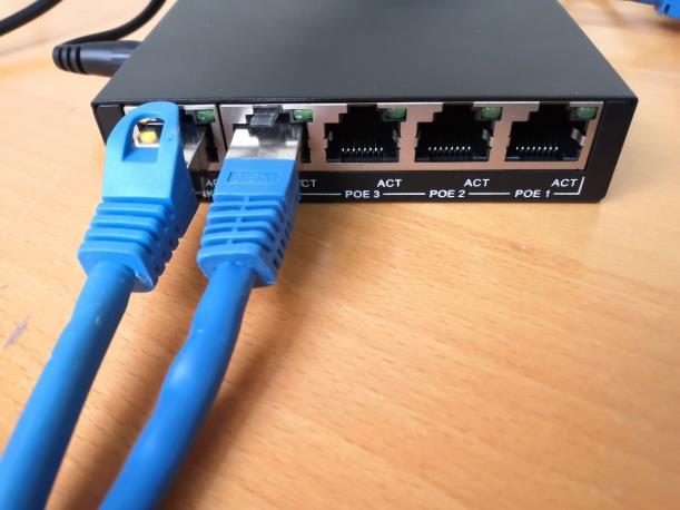
At the control room, install a network switch (see photo below) and connect the RJ45 network cable from the Lift to it.
Also connect a laptop or Multicam here. If you have one, you can also connect a control desk. Here is a possible installation diagram (the computer can be replaced by a multicam):
Once the network is set up and each device is powered on, you can do a quick check of the connections. A device is communicating if the LEDs on its network port are flashing. Note that the flashing does not necessarily have to be regular.
Identify connected devices
Now that all the devices are connected to the network, they must be configured to communicate between eu:Network Setupp